The 360 Systems frequency shifter is a really interesting and fairly rare piece of analog gear, and well suited for use with synthesizers. There are at least two different versions of this device, with the earliest ones housed in a green case...

... and the later versions, sporting some circuit upgrades, housed in a blue case.

I remember first reading about this as part of the equipment listed on the back of the excellent first album by Larry Fast/Synergy "Electronic Realizations For Rock Orchestra". You can see one of these sitting on the top of the Moog Modular 15 in his studio at that time...

I had no idea what it actually was, but MAN did it sound cool! FREQUENCY SHIFTER!
Larry not only helmed the many wonderful and inspirational Synergy releases, but also added his distinctive magic to albums and tours by Peter Gabriel, Nectar, Foreigner, and others. A true pioneer.
Thanks, Larry!

My unit is a very early one, I think. A look at the serial number would suggest that it might be made in early 1975, perhaps serial number 8? Maybe, maybe not.

There's quite a bit of rework going on underneath the board. This is often the case with very early boards, as mistakes are discovered and repaired to make the early units sellable. A close examination of this board showed that entire power supply was laid out backwards (!) so all the diodes and capacitors had to be installed backwards to make it work correctly. The blue jumper wires make the proper connections here and there, and parts that were either forgotten or added later to make things work correctly are soldered on back here as well. I really like the 360 logo etched into the board. If you look closely, you can see that they actually used it to connect two traces!

The print ad for this (thanks, Riley!!) at the time made some very interesting suggestions about the capabilities of this unit, in typical 1970's flair....

Turn a violin into flannel bass??!??!? What the what? Good God, Y'all!
Those with sharp eyes will note that the case shown in this ad isn't the same case used in either the green or the blue production versions. This picture was probably the original proto unit.
As I mentioned earlier in my blog, I acquired one of the earlier green ones along with my Moog 55, and after a few simple mods and some recalibration, I was able to use it on various projects for a number of years. I remember calling the good people at 360 Systems at the time I got it to see if I could get a schematic, and it took a while for them to actually locate one at the factory! I eventually got a huge blueprint-size schematic in the mail, free of charge. Impressive customer service!
The most useful mod to it at the time was replacing some of the single turn trimmer pots in the balanced modulator sections with 12 turn trimmer pots, to allow for a more accurate calibration (the four green rectangles at the bottom left quadrant).

Adusting these pots allows you to reduce the amount of background noise and signal bleedthrough, and with the new more accurate trimmers in place, calibrating it was much easier, and improved the performance by a noticeable amount. I also at that time upgraded the generic opamps in the audio path with quieter devices.
In use, there are some pretty interesting effects to be had from this device. As you turn the shift knob, one output shifts things upward by the frequency set on the shift knob, while the other out shifts things down by the same amount. Things can get crazy pretty quickly!
With just a small amount of shift, and the up and down outputs panned hard left and right in a mix, a beautiful chorus sound is created, different from any others. It's said that the swirling "oooh" and "aaah" background vocals on Pink Floyd's song "The Great Gig In The Sky" are treated with a prototype frequency shifter, and that's what it sounds like to me...a sort of growly, swirly wonderfulness.

There's also a Ring Modulator output, to create all sorts of clangy, metallic timbres. I read somewhere that John McLaughlin used one of these units in the mid 70's with a footpedal to sweep the oscillator, and that seems likely to me as well...imagine the hyper-speed metallic goodness. Go Johnny, Go!

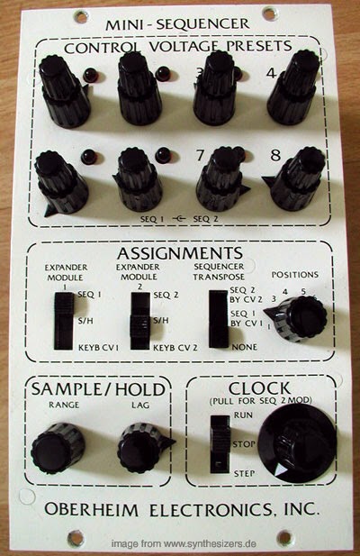
Ring modulators were starting to enjoy some well-deserved popularity in the early 70's. Oberheim built a stand-alone effects box type device (dig those crazy graphics!!!)...

...and also built a slightly modified version for sale by Maestro (they look quite a bit alike, eh?).

Artists like Jon Lord, Joe Zawinul and Jan Hammer were soon using them on their electric pianos and organs to produce a more interesting synth-like texture and create a pitch bend effect for solos.



For many artists at the time, this often served as a gateway (or at least a sideways entrance) to using synthesizers like the Minimoog or the Arp 2600, as they became more readily available.
I loaned my 360 Systems Frequency Shifter out to a friend, who at some point apparently decided that it was now his. When I finally got the unit back, he had proceeded to remove the circuit board, discard the case, and mount it into a single rack space casing. Like most of his (always very nicely made) devices, it was basic black, and all knobs, jacks and switches were unmarked. Feh.

After a number of phone calls, I was luckily able to track down the original case languishing in the back rooms of a recording studio (thanks, Roger!), and decided that when I got the time, I would restore it to its former 70's glory. The case had faded and discolored somewhat with time, but I still loved the sheer weirdness and funky mojo of the overall package.
GREEN! It's really an underused color.
My original schematic had gone missing, but after some sleuthing, I found a copy on the internet. I'll publish it here for those who might be interested. This would seem to be the scematic for the later model blue Frequency Shifter, as it differs in some areas from the components used in my unit, and the date on the print is from 1976. It was however plenty close enough to allow me to identify all of the necessary wiring locations on the circuit board to successfully transplant the board back into the original enclosure.
This looks remarkably similar to a schematic I saw in Electronotes back then for this type of device. It's certainly possible that one might have inspired the other...

Some important parts were missing. The original power transformer was gone, as was the cool green illuminated power switch and original potentiometers.
This also seemed like a good time to replace the electrolytic capacitors, as they were now 40+ years old, and the rubber seals were dried and cracked. The opamps in the audio path had already been upgraded a number of years ago, and I also wanted to extend the frequencies of the shift oscillator, and provide better CV control of the shift frequencies so I could easily control it from the Moog 55 and other devices.
The original unit had line level and instrument level outputs ( just the line level outputs scaled down with a resistor divider). I thought that the panel space for the instrument level outs would be better served by making them the inverted phase versions of the line level jacks. This could make for some interesting stereo effects during shifting.
I found a transformer from Mouser Electronics that fit the same mounting holes, and was just a bit larger voltage-wise than the original. I also found a functional green illuminated power switch...nowhere near as cool looking as the original, but it would certainly do until a better replacement could be found. These were fitted, along with a new power cable and strain relief.


The front panel was cleaned, and the new power switch, jacks, knobs and pots were installed. You can see some of the discoloration around the screw holes, but it still looks pretty good, I think.
Adding the parts for the output inverters and the improved CV scaling would require the addition of a small board to hold the necessary circuitry, so I built everything on a small perfboard and mounted it to the inside front panel of the unit. This made wiring up the various outputs easy and kept the lead lengths short.

When I fired it up initially to take a look at everything, I found that that the transformer voltage was indeed too high. This made the voltage regulators on the main board overheat since they now had to dissipate the extra power to bring this higher voltage down to the required level at the main board.
I added a couple of small 5 watt resistors to each side of the transformer outputs to soak up the extra voltage, and secured them to the top of the transformer with some silicon rubber adhesive. This reduced the power dissipation of the regulator, and now things were running nice and cool again. I also upgraded the 12 turn trimmers to grey 20 turn trimmers, since one had gone intermittant after all these years.

To extend the frequencies of the shift oscillator, I bought a 5 position rotary switch to replace the original 3 position switch. Now I had a position below and a position above the original panel marking. I added the appropriate capacitors to the shift oscillator circuit for the two new positions, and that gave me a lower and higher shift range, as compared to the original circuit.
After a bit of wiring to connect all of the front panel controls, and some tesing to verify that all of the various circuits were functioning correctly, it was time to reassemble the board into the original case, and recalibrate the system.


The unit is still missing its unusual gigantic radio tuner dial to set the shift amount, but I believe that it's merely biding its time hiding in my storage space. Until it returns, I did manage to find a smaller version to keep the front panel from looking too barren.
And so here it is, in all of its Mighty Green 70's glory, its Mojo and Mighty Shifting Powers intact!
Good God, Y'all!


 Posted with Blogsy